
- Tassadaq
- Sep 16, 2026
- Buying Guides
CAN bus lets a vehicle’s electronic control units share information over a common network. Understanding its frame structure, wiring and diagnostic signals helps technicians trace communication faults without replacing parts by guesswork.
Modern vehicles coordinate dozens of electronic modules. The engine controller may need road speed from the ABS module, while the instrument cluster displays coolant temperature reported by the engine controller. A shared network reduces the separate signal wires needed to exchange that information.
This guide explains Classical CAN, CAN FD and CAN XL, then connects the protocol to practical checks at the wiring harness and OBD-II port. The key is to combine generic CAN principles with the wiring diagram and service procedure for the vehicle being tested.
What Is CAN Bus
CAN bus, short for Controller Area Network, is a serial communication standard that enables electronic control units to exchange messages over a shared pair of wires without a host computer. Nodes on the same bus segment can observe its traffic; acceptance filters determine which messages a controller passes to its application. Each message carries an identifier rather than a destination address, and that identifier also sets its priority on the bus.
The standard is defined by the ISO 11898 family. ISO 11898-1 covers the data link layer and the way bits are coded. ISO 11898-2 covers the high-speed physical layer, the physical layer discussed in the voltage and termination examples below.
A Short History
Bosch began developing CAN in 1983 and released the protocol publicly in 1986 at the SAE conference in Detroit. Intel shipped the first CAN controller chips in 1987, with Philips following shortly after. The first production car to use a CAN-based multiplex wiring system was the Mercedes-Benz W140, released in 1991. ISO published the standard as ISO 11898 in 1993.
Bosch also published the CAN 2.0 specification in 1991, split into Part A for the 11-bit identifier format and Part B for the 29-bit extended format. You will still see controllers described as CAN 2.0A or CAN 2.0B for that reason.
How CAN Bus Works
Differential signalling on a twisted pair
High-speed CAN runs on two wires, CAN High and CAN Low, twisted together. The receiver measures the voltage difference between them rather than either wire against ground.
When the bus is idle, both wires sit at roughly 2.5 V. This is the recessive state and represents a logical 1. To send a dominant bit, a logical 0, the transceiver drives CAN High up to around 3.5 V and CAN Low down to around 1.5 V.
Twisting the pair means any electrical noise picked up from an ignition coil, alternator or injector driver hits both wires almost equally. The differential receiver rejects much of this common-mode interference, within its operating limits. That noise tolerance helps CAN communicate reliably in an engine bay.
Dominant beats recessive
The whole protocol rests on one electrical rule. If any node on the bus transmits a dominant bit while another transmits a recessive bit, the bus goes dominant. A dominant differential state overrides a recessive state; CAN High and CAN Low should not be confused with logical high and low on a single wire.
That rule determines which node transmits first and allows a node to flag an error by asserting dominant bits.
Arbitration without collisions
Any node may start transmitting when the bus is idle. If two start at the same instant, they both transmit their identifier bit by bit and monitor the bus while they do it.
The moment a node sends a recessive bit and reads back a dominant one, it knows a higher priority message is in progress. It stops transmitting and becomes a receiver. The winning node continues its frame without interruption.
This process is called non-destructive bitwise arbitration. Among competing base-format data frames with different identifiers, the lower identifier wins. The losing transmitter waits for another opportunity. Arbitration itself does not corrupt the winning frame, although electrical faults and other protocol errors can still disrupt communication. Network designers assign priorities according to the application’s timing requirements.
Classical CAN Frame Structure
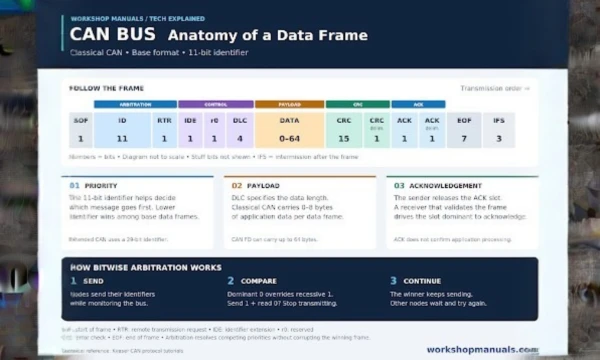
Figure 1. Classical CAN base-format fields and arbitration. Graphic: WorkshopManuals.com.
A Classical CAN base-format data frame contains the following fields. Intermission follows the end of the frame; the bit counts exclude inserted stuff bits.
|
Field |
Bits |
Purpose |
|---|---|---|
|
Start of frame |
1 |
Dominant bit that synchronises every node |
|
Identifier |
11 |
Message ID and priority |
|
RTR |
1 |
Marks a data frame or a remote request |
|
IDE |
1 |
Selects 11-bit or 29-bit identifier format |
|
r0 |
1 |
Reserved |
|
DLC |
4 |
Number of data bytes that follow |
|
Data |
0 to 64 |
The payload, 0 to 8 bytes |
|
CRC |
15 |
Error-detection sequence calculated from protected frame bits |
|
CRC delimiter |
1 |
Recessive |
|
ACK slot |
1 |
Any node that received the frame correctly drives this dominant |
|
ACK delimiter |
1 |
Recessive |
|
End of frame |
7 |
Recessive |
|
Intermission |
3 |
Minimum gap after the frame before normal transmission resumes |
The extended format carries a 29-bit identifier and adds format-specific fields; it is more than a simple substitution in the table above. Higher-layer protocols such as SAE J1939 use extended identifiers on trucks and agricultural equipment.
The acknowledgement slot is worth understanding when you are diagnosing a fault. The transmitting node sends that bit recessive and expects at least one other node to overwrite it with a dominant bit. If nobody does, the transmitter treats the frame as failed and retries. Without an acknowledging receiver, repeated ACK errors can make a transmitter error-passive. This is not the same as proving that the transmitting module is defective; retransmission also depends on controller configuration.
CAN Standards and Physical Layers
|
Standard |
What it covers |
|---|---|
|
ISO 11898-1 |
Data link layer and physical coding sublayer, including CAN FD |
|
ISO 11898-2 |
High-speed physical layer; capability depends on the transceiver and protocol |
|
ISO 11898-3 |
Low-speed fault-tolerant physical layer, can tolerate certain single-wire faults |
|
ISO 11898-5 |
Historical reference for high-speed low-power operation; check the applicable ISO 11898-2 edition |
|
ISO 11898-6 |
Historical reference for selective wake-up; check the applicable ISO 11898-2 edition |
|
ISO 15765 |
Diagnostics over CAN, including the OBD-II profile |
|
SAE J1939 |
Higher layer protocol for trucks and buses |
|
ISO 11783 |
J1939 variant for agricultural machinery |
|
SAE J2411 |
Single-wire CAN, used by GM as GMLAN |
|
NMEA 2000 |
J1939-based protocol for marine electronics |
Low-speed fault-tolerant CAN under ISO 11898-3 is the one people forget. It is common on body and comfort networks, typically runs at 125 kbit/s or less, and can maintain communication through certain single-wire faults. If you probe a body CAN circuit expecting the 60 ohm reading of a high-speed bus and do not get it, check which physical layer the network actually uses before condemning anything.
Comparing Classical CAN CAN FD and CAN XL
CAN FD expands the payload and permits a faster data phase than Classical CAN. CAN XL extends payload capacity further. These formats require compatible controllers, transceivers and network design; their maximum capabilities are not guaranteed on an existing harness.
|
Feature |
Classical CAN |
CAN FD |
CAN XL |
|---|---|---|---|
|
Maximum payload |
8 bytes |
64 bytes |
2048 bytes |
|
Bit rate |
Up to 1 Mbit/s |
Arbitration up to 1 Mbit/s, data phase commonly 2 to 5 Mbit/s |
Up to 20 Mbit/s |
|
Identification |
11-bit or 29-bit identifier |
11-bit or 29-bit identifier |
11-bit priority ID with additional addressing fields |
|
Remote frames |
Supported |
Not supported |
Not supported |
When bit-rate switching is enabled, CAN FD transmits its data phase faster than its arbitration phase. Receivers still synchronize and sample the incoming bits. Separate data-phase timing and suitable transceivers allow the higher rate after arbitration has selected one transmitter. CAN FD uses a 17-bit or 21-bit CRC sequence, depending on payload length.
A larger payload and faster data phase can shorten ECU programming transfers and support higher-bandwidth control messages. Actual performance depends on bus loading, message scheduling and the physical network.
CAN Bus Wiring and Termination
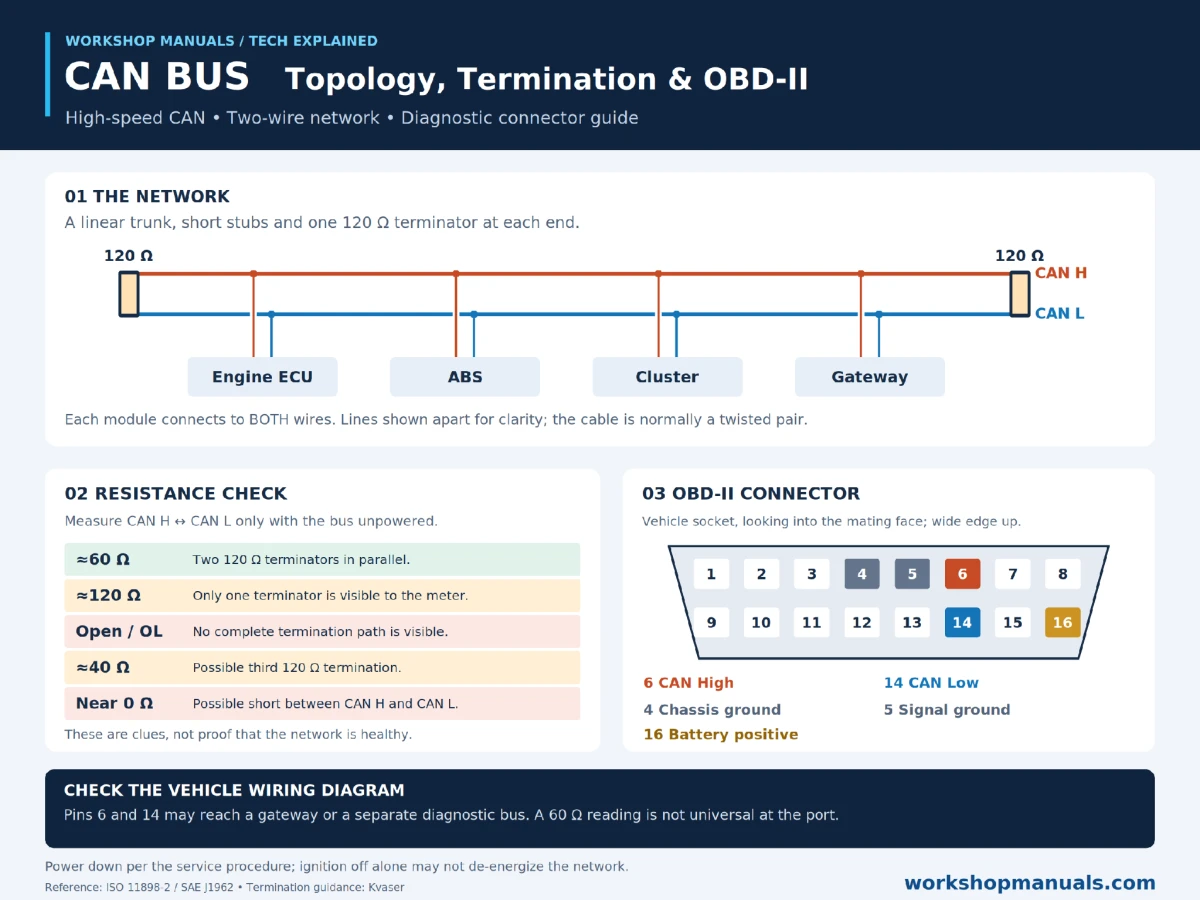
Figure 2. High-speed CAN wiring, resistance clues and OBD-II pin assignments. Graphic: WorkshopManuals.com.
A conventional high-speed CAN segment uses a linear trunk with short branches, or stubs, to its modules. Excessive stub length can create reflections and reduce signal quality. Vehicle networks may contain several segments joined by gateways.
A conventional segment has a 120-ohm terminating resistor across CAN High and CAN Low at each physical end. With the network unpowered and both terminations visible from the test point, the two resistors appear in parallel and measure approximately 60 ohms. Follow the manufacturer’s power-down procedure; switching off the ignition alone may leave modules awake.
Use resistance measurements as clues, not conclusive diagnoses:
-
Around 60 ohms: consistent with two 120-ohm terminations in parallel. It does not prove every branch, module or signal is healthy.
-
Around 120 ohms: only one termination may be visible because of an open circuit, disconnected section or missing terminator.
-
Open circuit or OL: no complete termination path is visible from the probes. Check probe contact, wiring and network architecture.
-
Around 40 ohms: may indicate three 120-ohm terminations in parallel.
-
Near zero ohms: suggests a short between the lines or another low-resistance path.
The OBD-II port may connect through a gateway or to a separate diagnostic segment. Do not assume every vehicle must measure 60 ohms across pins 6 and 14.
CAN Bus and the OBD II Connector
For US-market light-duty vehicles, CAN became the required OBD-II communication protocol from the 2008 model year. Earlier vehicles may use SAE J1850 PWM, SAE J1850 VPW, ISO 9141-2 or ISO 14230 KWP2000. OBD-II defines diagnostic access; it does not describe every network inside the vehicle.
SAE J1962 defines the 16-pin diagnostic connector, usually found beneath the dashboard near the driver. For CAN diagnostics, identify these pins using the vehicle-side socket orientation shown in the infographic:
|
Pin |
Signal |
|---|---|
|
4 |
Chassis ground |
|
5 |
Signal ground |
|
6 |
CAN High |
|
14 |
CAN Low |
|
16 |
Battery positive |
Pins 6 and 14 serve CAN diagnostics, but populated terminals alone do not prove which protocol is active. Confirm it with the service information or scan tool. Legacy protocols use other terminals, including pins 2 and 10 for J1850 and pins 7 and, where applicable, 15 for K-line diagnostics.
ISO 15765-4 includes combinations of 11-bit or 29-bit identifiers and 250 or 500 kbit/s operation. Use the vehicle’s specified configuration rather than inferring it from vehicle size.
On Classical CAN, ISO-TP divides longer diagnostic messages across multiple frames. With normal addressing, a single frame carries up to 7 bytes of diagnostic data after its protocol byte; addressing formats can change the available capacity. Longer responses start with a first frame declaring the total length, the receiver replies with a flow control frame setting the pacing, and the sender then streams consecutive frames.
Diagnosing CAN Bus Faults
Start with the vehicle’s network diagram, symptom history and a complete scan. Communication faults can arise from wiring, module power supplies, grounds, transceivers, configuration or gateway behavior. A useful sequence is:
-
Record the fault pattern. Note which modules respond, collect U-codes and confirm battery voltage and relevant module power and ground supplies.
-
Check resistance with the network unpowered. Follow the service procedure and measure at a verified CAN test point. Apply the resistance clues above only to the appropriate physical layer and segment.
-
Measure line voltage under the specified operating conditions. Conventional high-speed CAN typically rests near 2.5 V on both lines. A multimeter shows an average during traffic, not individual bits. Investigate a line held near ground or battery voltage.
-
Scope both lines. Compare the differential signal, amplitude and edges with the service specification. A flat or distorted trace may indicate wiring, loading, transceiver or power problems; it does not by itself distinguish a module fault from a harness fault.
-
Isolate branches as directed by the wiring diagram. Power down before disconnecting components where required. If communication returns, inspect both that branch and its module before condemning a part. Removing a module may also remove a terminator.
Bus routing, gateway connections, terminator locations, connector pinouts and wire colors vary by manufacturer and model. Generic OBD-II exposes standardized emissions information but may not reach every module or manufacturer-specific data item. Consult the vehicle’s factory workshop manuals for the wiring diagrams and diagnostic procedures that turn a general CAN test into a model-specific investigation.
Other Vehicle Networks
CAN is not alone in a modern vehicle. It sits alongside several other networks, each chosen for cost and bandwidth.
|
Network |
Typical speed |
Typical use |
|---|---|---|
|
LIN |
Up to 20 kbit/s |
Single-wire, low-cost subsystems: mirrors, seats, window motors |
|
CAN |
Up to 1 Mbit/s |
Powertrain, chassis, body, diagnostics |
|
CAN FD |
Several Mbit/s in the data phase |
Higher bandwidth control, ECU flashing |
|
FlexRay |
10 Mbit/s |
Time-deterministic chassis control, active suspension, x-by-wire |
|
Automotive Ethernet |
100 Mbit/s to multi-gigabit |
Cameras, ADAS sensor data, infotainment |
A central gateway module forwards messages between these networks. That gateway is also why a scan tool plugged into the OBD-II port can reach a module that is not physically on the diagnostic bus at all.
Advantages and Disadvantages of CAN Bus
Advantages
-
Large reduction in wiring weight, cost and connector count
-
Non-destructive arbitration preserves the winning frame when priorities compete
-
Priority is built into the message identifier rather than managed by a host
-
Strong error detection through CRC, bit monitoring, stuffing rules, form and acknowledgement checks
-
Error counters constrain repeated protocol errors, although physical shorts can still disable communication
-
Multi-master access avoids a central bus controller; adding modules still requires compatible configuration and timing
Disadvantages
-
Payload of 8 bytes in classical CAN is small, and longer data needs a transport protocol
-
Maximum speed of 1 Mbit/s is far below what camera and radar data needs
-
Bus length and speed trade off against each other, so a long bus must run slower
-
No built-in security. Any node with bus access can transmit any identifier, which is the root of most vehicle network attacks
-
Broadcast traffic reaches the segment’s controllers, though acceptance filters reduce application processing
Frequently Asked Questions
What does CAN stand for
Controller Area Network. It is a serial bus standard originally developed by Bosch for road vehicles and now used in industrial, agricultural, marine and medical equipment.
Why should a healthy CAN bus measure 60 ohms
Two 120-ohm end terminations on a conventional high-speed segment appear as roughly 60 ohms in parallel when the network is unpowered. Gateways and other architectures can change what is visible at the diagnostic port; the reading does not prove the whole network is healthy.
What is the difference between CAN High and CAN Low
They are the two halves of a differential pair. At rest both sit near 2.5 V. To send a dominant bit, CAN High is driven up to around 3.5 V and CAN Low down to around 1.5 V. The receiver reads the difference between them.
Is CAN bus the same as OBD-II
No. OBD-II is the diagnostic standard. CAN is one of the lower layer protocols OBD-II can run over, and since the 2008 model year in the United States it is the only one permitted, defined by ISO 15765-4.
Can CAN FD replace classical CAN on existing wiring
Not automatically. Reusing a harness requires checking topology, transceiver capability, timing and signal integrity at the intended data rate. Nodes that observe FD traffic must support it or be explicitly designed to tolerate it; ordinary Classical CAN controllers may signal errors.
How many bytes can one CAN message carry
Classical CAN carries up to 8 bytes. CAN FD extends this to 64 bytes, and CAN XL to 2048 bytes.
Putting CAN Bus Knowledge to Work
CAN combines differential signaling, message priorities and error detection to move information between vehicle modules. Understanding the frame explains how messages travel; understanding the wiring explains where to measure and what a reading can reveal.
Use resistance, voltage, waveforms and scan results together. Check each finding against the vehicle’s network diagram before replacing a component. That approach narrows the fault systematically and avoids treating a generic CAN rule as a diagnosis.
Comments